新闻资讯NEWS |
文章详细Siemens PLC fault detection method
专栏:other
发布日期:2017-12-25
阅读量:2912
收藏:
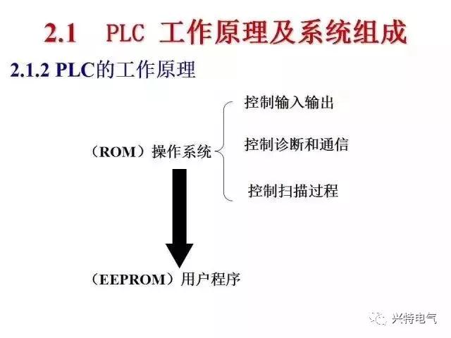
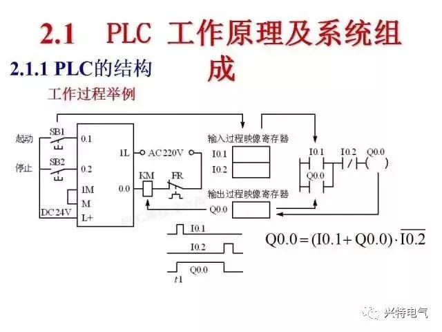
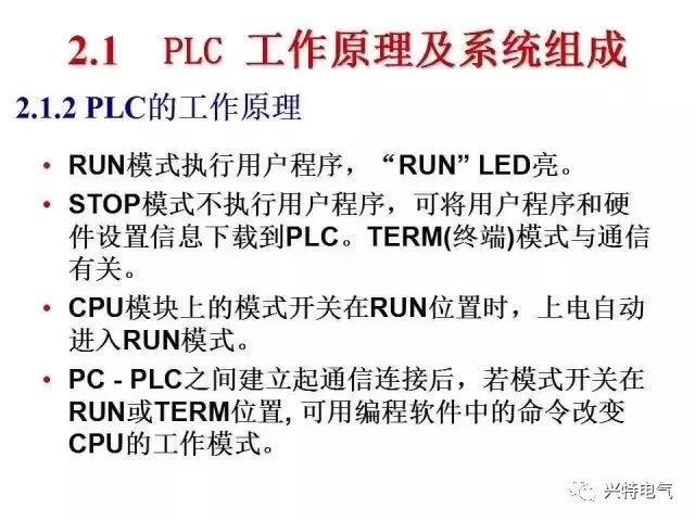
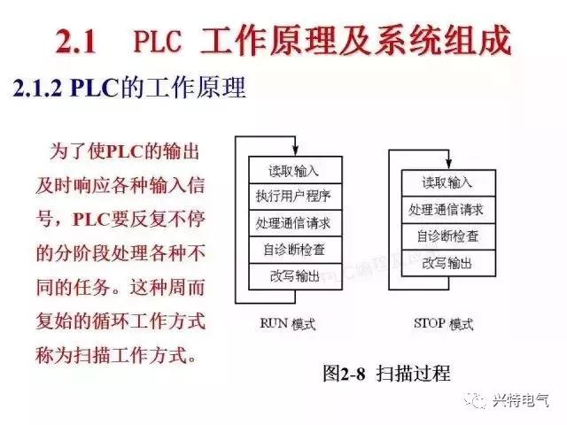
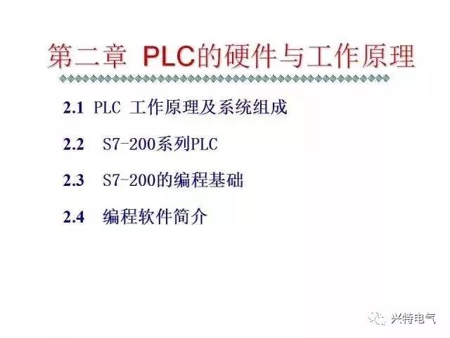
When it comes to PLC fault, let's talk about the hardware and working principle of Siemens PLC first. Different PLCS have different programming methods.
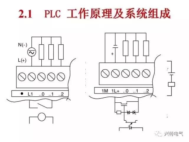
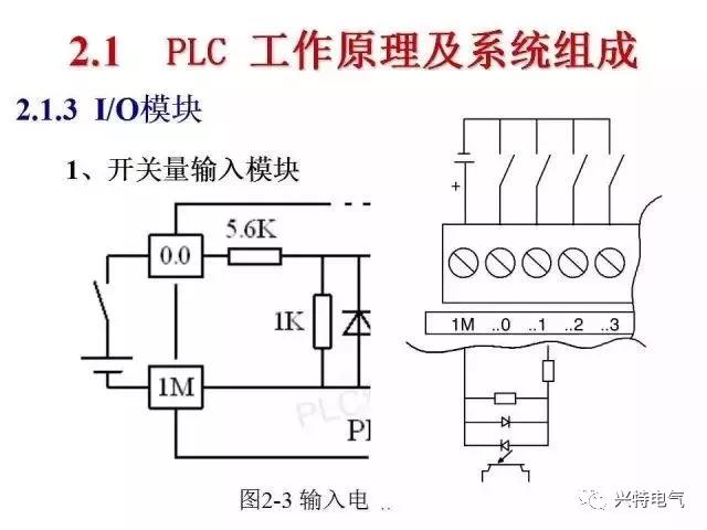
After looking at the hardware structure and working principle of Siemens PLC, let's look at the common hardware failure reasons of PLC. PLC hardware fault can be found more intuitively,The basic method of maintenance is to replace the module。Judging the fault module according to the fault indicator light and the fault phenomenon is the key to maintenance, and blind replacement will bring unnecessary losses. 1. Power module failure A normal working power supply module, the above work indicator light such as "AC", "24VDC", "5VDC", "BATT" should be green long bright, which light color has changed or flicker or off that part of the power supply problem. "AC" light means the total AC power supply of PLC, "AC" light is not bright most of the power supply, the whole PLC stop. At this time should check whether the power fuse fuse, fuse replacement is the application of the same specifications with the same type of fuse, no same type of imported fuse to replace the current of the same fast fuse. If repeated fuses indicate circuit board short circuit or damage, replace the entire power supply. When the "5VDC" and "24VDC" lights are off, it means that there is no corresponding dc power supply output. When the power supply deviation exceeds 5% of the normal value, the indicator light flashes. At this time, although the PLC can still work, it should be paid attention to and shut down for maintenance when necessary. "BATT" color changing light is the backup power indicator light, green normal, yellow low power, red fault. When the yellow light is bright, the backup battery should be replaced. According to the manual, lithium battery should be replaced once every two to three years. When the red light is bright, it means that the backup power system fails and the entire module needs to be replaced. 2. I/O module failure The input module is generally composed of photoelectric coupling circuit. The output modules are relay output, transistor output, photoelectric output and so on. Each point of input and output have corresponding led indication. The I/O module should be suspected to have a fault if there is an input signal but the point does not light up or if there is a certain output light but the output light does not light up. The input and output modules have 6 to 24 points, and it is not economical to replace the entire module just because one point is damaged. The usual approach is to find an alternate point and change the address in the program. But it should be noted that the larger program is difficult to find a specific address. It is particularly emphasized that no matter the replacement of the input module or the output module, it should be carried out in the case of PLC power failure. The S5 live plugging module is absolutely not allowed. 3. CPU module failure General type S5PLC CPU module often includes communication interface, EPROM slot, running switch, etc., the fault is more hidden, because the cost of replacing the CPU module is very large, so its fault analysis, judgment to be particularly careful. Maintenance example: when a PLC switches on the power supply, it is unable to turn the switch to RUN state. The error indicator light first flashes and then turns on normally. After power off and reset, the fault remains. The CPU was replaced during the chip-level maintenance, but the failure light still kept flashing. The function did not return to normal until the communication excuse board was replaced. Changsha Hing special General Electric Co.Ltd Address: room 807, chuangye building, lugu enterprise square, no.27 wenxuan road, high-tech zone, changsha, hunan Telephone: 0731-88922097 88614760 88927559 89707759 Fax: 0731-88922440 下一页:找不到相关信息
|

